|
|
Post by lmadsen on Mar 8, 2024 5:18:40 GMT
Thank you for the video and manual on the Crossing Gate. The base of my crossing gate does not look like the ones in the manual or on the video. As you can see from the picture, I do not have clips on the bottom. I only have wiring coming out of the base. So. . .I do not know how to connect the wires to make the crossing gate function. I did get the lights to work when I tied the two short red wires together and connected those and the short black wire to a power source. Connecting the black and red long wires to a power source did not make the gate work. I would appreciate any suggestions you might have. Thanks, Larry 
|
|
|
|
Post by lmadsen on Mar 9, 2024 4:25:35 GMT
I am seeing that many people have viewed my request for help on my crossing gate but have seen no help. I am assuming I have something that is very questionable and probably will not be made to function. Any thoughts will be greatly appreciated. Thanks Larry
|
|
|
|
Post by dlagrua on Mar 9, 2024 11:11:45 GMT
My logical guess. I would say the black wires and the red wires go together. Then you will have two connections to supply the closing action and the lights
|
|
|
|
Post by Adam on Mar 9, 2024 11:39:48 GMT
I think dlagrua is correct. Seems like someone may have reimagined how this particular one should be wired at some point.
|
|
|
|
Post by Traindiesel! on Mar 12, 2024 1:27:28 GMT
You may need to use a little Yankee Ingenuity. To work correctly you’ll need the 153C Contactor to start.
|
|
|
|
Post by af3020 on Mar 13, 2024 16:12:04 GMT
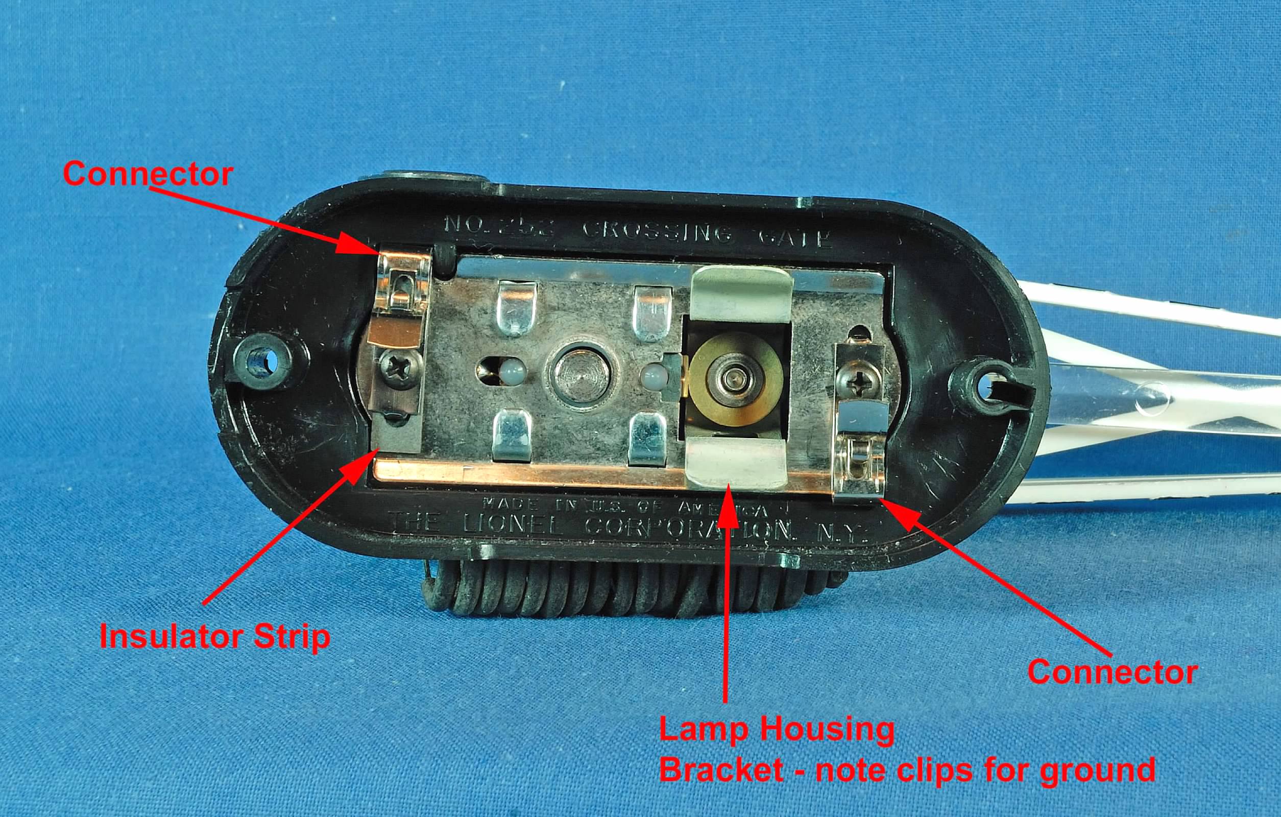
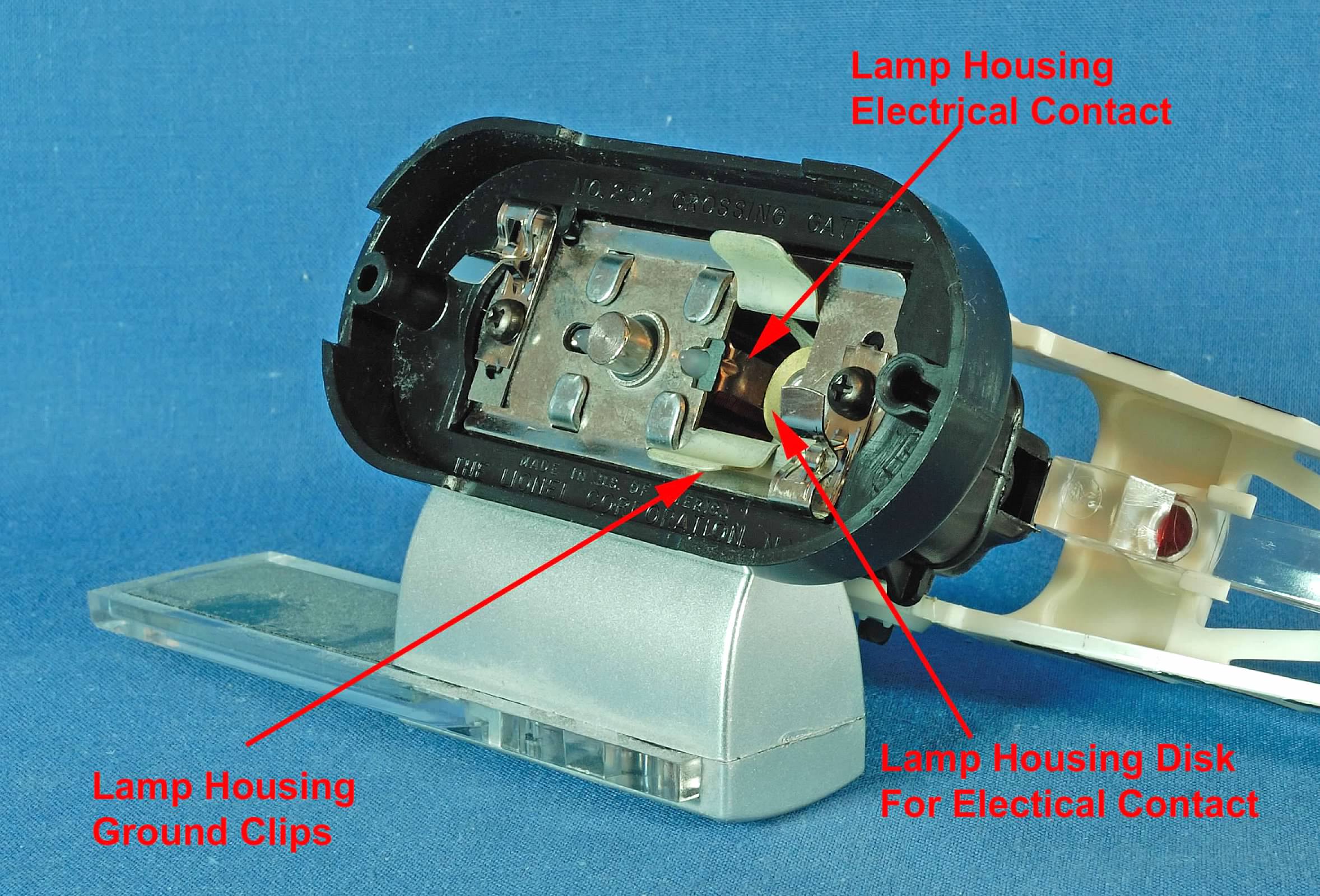
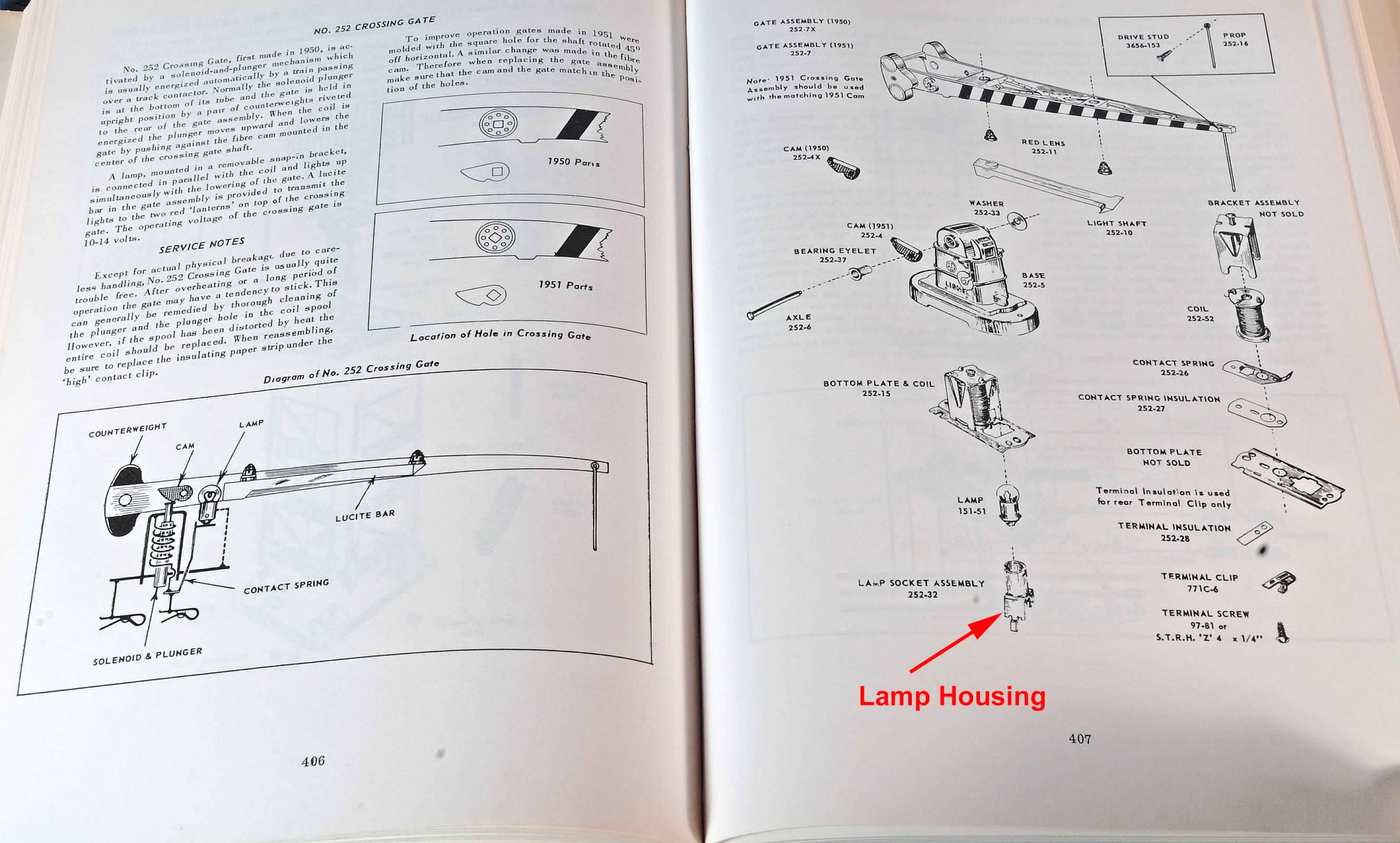
Based on what you have pictured it looks like someone, for whatever reason, trashed the lamp socket (housing) and the two electrical connectors. It also looks like (for reasons unknown) that they filed or cut out a spot on the edge of the assembly and ran three wires through it. Given that they don't have the lamp socket they would have to run two wires to connect the lamp to some kind of other housing and given that they don't have the electrical connectors, nor the insulation strip that goes underneath one of them, they would have had to run two additional separate wires to power the coils for the solenoid to activate the plunger. As you can see from the repair manual diagram, at the most that would mean 4 additional wires. In order to understand the why of that additional wire you will have to take your crossing apart and check it over.   Lionel Repair Instructions  I hope this will help you get your crossing gate up and running. |
|